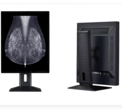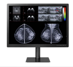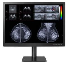
The gap between medical display quality and COTS (commercial-off-the-shelf) is quickly coming down to just the attributes added by the medical display manufacturer to stabilize the back lights and incorporate a look-up-table (LUT) for compliance to DICOM Part 3.14, grayscale standard display function (GSDF).
However, performance minimums for primary reading, LUTs and back light stabilization maintain the divide between displays that meet radiology reading requirements and those that target the consumer.
Next Generation Speeds Up
The Cadillac standard for radiology has been the Dual Domain In-Plane-Switching (DIPS) technology found both in monochrome and color AM-LCD cores. The key attributes are off-axis viewing characteristics that influence luminance roll-off, contrast stability and minimal clipping of the red wavelength. An alternative core technology found in COTS displays is Vertical Alignment (VA), which has provided faster switching speeds, but suffered from red clipping and uneven contrast roll-off.
The latest generation of AM-LCD cores using In-plane-Switching (IPS) and VA are faster and provide almost equal off-axis viewing characteristics. They are found in both COTS and medical displays at 1.3MP and 2.0MP. Three Megapixel and 5MP have few commercial applications, so medical vs. COTS is 2MP or less and the equivalent of 2MP based on pixel size. The latter being a 30-inch 4MP that is the same as two 2MP displays on a single glass substrate with a pixel size of 251 microns. Most 2MP fall within 10 microns of 251, while 1.3MP are upward of 294 microns on a 19-inch substrate.
Two Megapixel cores come in 19, 19.6, 20.1, and 21.3-inch diagonal. The 19-inch has 242 micron pixels and is closer to a 3MP diagnostic with 206 micron pixels. For radiology workstations, the ideal pixel size for the human visual system sensitivity is 200 microns at 0.66 meter. Selecting a 2MP display as a lower cost option should be done with a thorough test drive first to reveal any perceived mechanical noise (row/column structure) at 0.66 meter - not standing back at one meter plus in a store.
What to Look for in Performance
The performance minimums established by the American Association of Physicists in Medicine (AAPM) for primary reading (see Figure 1) are the main reason COTS displays fall short. The lower peak luminance is hampered more by the minimum luminance ratio and minimum black level above ambient. To achieve a minimum luminance ratio of 250:1, the peak luminance has to be greater than 250cd/m2 if just a minimum of ambient light is falling on the display surface. The vendor may spec a high number, but this is measured without regard to ambient conditions. A 300cd/m2 rated display with a 0.6cd/m2 off pixel value yields 500:1 (LR). But ambient conditions can be close to 1cd/m2 and with a minimum Lamb x 1.5 (ideally 4x) the display is down to 200:1. Secondary reading criteria are far less stringent (Fig 1) and well within a COTS displays performance capability. But they are still missing LUTs and back light stabilization.
Built-in Backlight Stability
Proper setup or the ergonomics of a multihead workstation should minimize head movement and off axis viewing angles, i.e., the viewing angle should be normal to the display (perpendicular). Add backlight stabilization and LUTs to IPS or VA core technology and a display well suited for radiology is born. Peak luminance levels have also been increasing for COTS displays so that their useful life as a reading platform can be extended beyond one year while meeting basic performance criteria per the American Association of Physicist in Medicine (AAPM, TG18 document).
Backlight stabilization electronics involves a precision photometer observing the net luminance of all the lamps. Not something to be added as an aftermarket device to a COTS display, but more frequent verifications of the peak luminance can be performed with a light meter and quality sneakers. Getting a LUT applied to the image can be achieved with software only or software with an API program writing a LUT to the graphic card memory. The accuracy will be limited to working in the 8-bit world since the graphic card outputs 8-bits per color (Red=Green=Blue produces white or a shade of gray).
Test Grayscale Quality
Medical displays produce highly accurate responses to the GSDF, and this is the key to quality medical images. The most accurate method is to pass the Presentation Values (PACS viewer program) untouched to the display with an internal 10 or 12-bit LUT (more is better here). Medical displays also utilize other resources such as time domain dithering to increase the pallet size; 766 logic levels for monochrome increases to 3061 pallet responses; color goes from 1785 to 6631. A COTS display will not have this functionality. However, a hardware device that replicates this function between the graphic card and a COTS display will produce similar compliance to the GSDF response curve (Fig 2).
The AAPM 1K QC Test Pattern provides the visual landmarks to determine if a COTS display provides a balanced response and distribution of Presentation Values. Obvious distortions such as contour lines indicate a poor distribution, but their absence does not mean all is visible. The grayscale sequence of squares around the center (QC Test Pattern) also contains small low contrast targets (in the corners) at 4 and -4 pixel values from the squares pixel value; if they are not visible the display is not suitable for primary reading. A subtle lung lesion or nodule is just as hard to see as the low contrast targets.
Achieving GSDF compliance in combination with the three minimums shown in Fig 1 on a COTS display makes an excellent secondary reading platform and if you are willing to make frequent calibration checks, can be used for primary reading within limits based on the modality spatial content, i.e., x-sectional, ultrasound, Nuc/PET can all be viewed on a 2MP display with confidence. Higher spatial content, DR/CR, is best viewed on a 3MP for optimum first look. DR/CR on 2MP COTS with GSDF compliance and AAPM minimums is less efficient, but can be used with digital tools to drill down into the image. The luminance range available on a COTS display impacts the ability to see low contrast targets. The smaller the range, the more compaction of the image data set. The AAPM minimums are just that … minimums.
Author: Ken Compton is an Imaging Consultant and Lecturer on Image QC.

 March 12, 2024
